Oscilloscopes are the unsung heroes of the electronics world, silently working behind the scenes to make our modern technological marvels possible. These fascinating instruments allow us to peer into the invisible realm of electrical signals, transforming abstract concepts into visual, analyzable waveforms. Whether you're a budding engineer, a curious student, or simply intrigued by the technology that powers our digital age, understanding oscilloscopes opens up a world of insight into the very fabric of our electronic universe.
The Oscilloscope: Your Window into the Electrical World
At its core, an oscilloscope is a sophisticated electronic instrument designed to graphically display varying signal voltages as a function of time. Imagine it as an automated graph-drawing machine, capable of capturing and visualizing electrical waveforms with remarkable speed and precision. This ability to "see" electricity in action makes oscilloscopes indispensable tools in fields ranging from electronics design and repair to medical diagnostics and scientific research.
The fundamental purpose of an oscilloscope is to plot voltage (displayed on the vertical axis) against time (shown on the horizontal axis). This seemingly simple function belies the complex technology and principles at work within these devices. Modern oscilloscopes can display multiple channels simultaneously, allowing for the comparison of different signals, and often come equipped with advanced measurement and analysis tools to dissect signal characteristics with microscopic precision.
The Journey from Signal to Screen: How Oscilloscopes Work
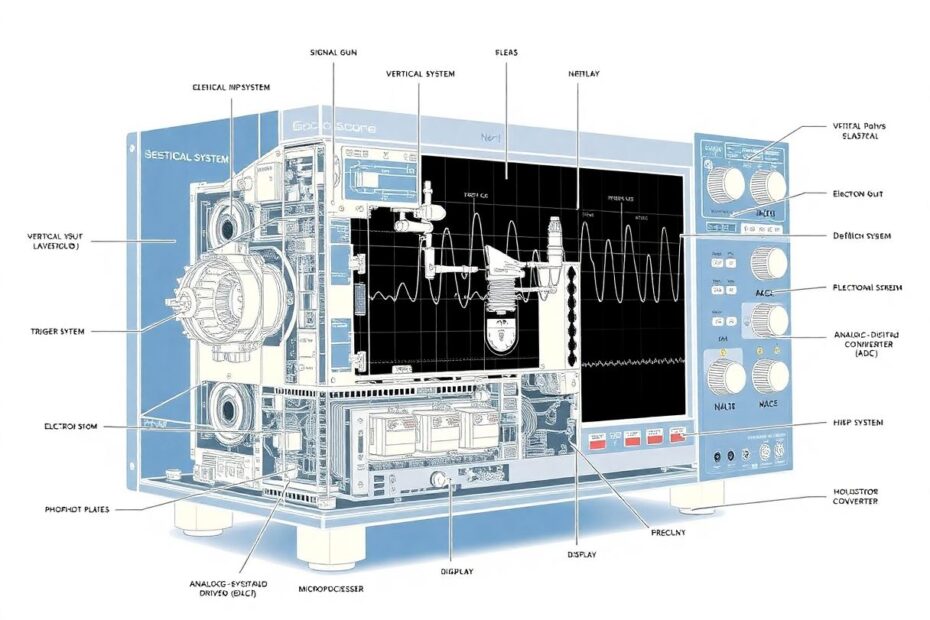
To truly appreciate the marvel of oscilloscope technology, let's embark on a journey through the inner workings of these devices, following an electrical signal from input to display.
Step 1: Signal Input – The Gateway to Analysis
Our journey begins when an electrical signal is connected to the oscilloscope's input through a probe. This probe is more than just a simple wire; it's a carefully designed interface that can attenuate (reduce) the signal if necessary and provide a high-impedance connection to avoid interfering with the circuit being measured.
Modern oscilloscope probes often include features like switchable attenuation (typically 1x or 10x), bandwidth compensation, and even active circuitry for improved performance at high frequencies. The choice of probe can significantly impact measurement accuracy, especially when dealing with high-frequency signals or low-amplitude measurements.
Step 2: The Vertical System – Scaling and Positioning
Once the signal enters the oscilloscope, it encounters the vertical system. This crucial component is responsible for scaling the input signal and positioning it appropriately on the display. The vertical system's tasks include:
Attenuation or Amplification: Depending on the signal's amplitude, the vertical system may need to reduce (attenuate) or increase (amplify) the signal to fit it within the display's range. This process ensures that signals of various magnitudes can be visualized effectively.
Analog-to-Digital Conversion: In digital oscilloscopes, which now dominate the market, the analog input signal must be converted into digital data. This is accomplished through high-speed Analog-to-Digital Converters (ADCs). The resolution of these ADCs, often expressed in bits, determines the oscilloscope's vertical resolution. High-end oscilloscopes may feature 12-bit or even 16-bit ADCs, allowing for extremely precise voltage measurements.
Vertical Positioning: The system allows users to adjust the vertical position of the trace on the screen. This feature is particularly useful when comparing multiple signals or focusing on specific voltage levels.
Voltage Scale: Often referred to as "volts per division," this setting determines the relationship between the signal's voltage and its visual representation on the screen. Modern oscilloscopes typically offer a wide range of voltage scales, from millivolts to tens of volts per division, accommodating signals of vastly different amplitudes.
Step 3: The Horizontal System – Time Base and Sweep
While the vertical system manages the signal's amplitude, the horizontal system controls how the signal is displayed over time. This system is often called the "time base" and is responsible for several key functions:
Time Base Setting: This crucial parameter determines how much time each horizontal division on the screen represents. It can range from nanoseconds per division for capturing high-speed events to seconds or even minutes per division for observing slow-changing phenomena.
Sweep Generation: The horizontal system creates a "sweep" – a controlled movement of the signal trace from left to right across the screen. In digital oscilloscopes, this is achieved through precise timing of the ADC sampling and display updates.
Sample Rate: A critical specification in digital oscilloscopes, the sample rate determines how many times per second the input signal is sampled. Higher sample rates allow for more accurate representation of high-frequency signals and can capture fast transient events that might be missed at lower rates.
Horizontal Position: Users can adjust the trigger point's horizontal position, effectively shifting the waveform left or right on the display. This feature is invaluable when focusing on specific portions of a signal or when aligning multiple waveforms for comparison.
Step 4: The Trigger System – Stabilizing the Display
Without a robust trigger system, an oscilloscope's display would be a chaotic, constantly shifting mess of lines. The trigger ensures that the waveform starts drawing at the same point on successive sweeps, creating a stable, readable image. Here's how it works:
Trigger Level: Users set a specific voltage level at which they want the oscilloscope to initiate a sweep. When the input signal reaches this level, it "triggers" the start of a new trace.
Trigger Source: The trigger can be derived from various sources, including the input signal itself (most common), an external trigger input, or even the power line frequency for certain applications.
Trigger Modes: Oscilloscopes typically offer several trigger modes to suit different measurement needs:
- Auto mode: The oscilloscope will sweep periodically even if no trigger is detected, useful for initial signal exploration.
- Normal mode: The oscilloscope only sweeps when a trigger event occurs, ideal for capturing infrequent events.
- Single mode: The oscilloscope captures one trace upon receiving a trigger and then stops, perfect for capturing one-time events or for detailed analysis of a specific waveform.
Advanced Trigger Types: Modern oscilloscopes offer sophisticated triggering options beyond simple level triggering. These can include:
- Edge triggering: Initiates a sweep on rising or falling edges of the signal.
- Pulse width triggering: Triggers based on the duration of pulses in the signal.
- Logic triggering: Allows triggering based on combinations of conditions across multiple channels.
- Protocol-based triggering: Specialized triggers for analyzing digital communication protocols like I2C, SPI, or USB.
Step 5: From Electrons to Images – The Display System
The final step in our journey is the creation of the visible trace on the oscilloscope's display. The method by which this is achieved has evolved significantly over the years:
Cathode Ray Tube (CRT) Oscilloscopes:
While largely superseded by digital technology, understanding CRT oscilloscopes provides valuable insight into the instrument's history and fundamental principles:
- An electron gun emits a focused beam of electrons.
- The vertical and horizontal systems control electromagnetic deflection plates.
- These plates steer the electron beam across a phosphor-coated screen.
- Where the beam strikes, the phosphor glows, creating the visible trace.
- The persistence of the phosphor allows the human eye to perceive a continuous waveform, even though the beam is actually sweeping rapidly across the screen.
Digital Oscilloscopes with LCD or LED Displays:
Modern digital oscilloscopes use a fundamentally different approach:
- The processed digital signal data is stored in high-speed memory.
- A microprocessor uses this data to calculate which pixels on the display should be illuminated.
- The display is continuously updated, creating the illusion of a moving waveform.
- Advanced display technologies like LED backlighting and high refresh rates ensure crisp, clear waveform visualization.
Digital oscilloscopes offer numerous advantages over their CRT predecessors, including higher update rates, the ability to display multiple channels with different colors, and features like zoom and pan for detailed waveform analysis.
Beyond the Basics: Advanced Features of Modern Oscilloscopes
As technology has advanced, oscilloscopes have evolved far beyond simple voltage-versus-time displays. Modern instruments offer a wealth of advanced features that expand their capabilities and ease of use:
Multichannel Inputs: Most oscilloscopes now offer two or four input channels, with some high-end models featuring even more. This allows for simultaneous comparison of multiple signals, essential in complex circuit analysis and system debugging.
Math Functions: Built-in mathematical operations allow users to perform calculations on signals in real-time. Common functions include addition, subtraction, multiplication, and integration of waveforms.
FFT Analysis: Fast Fourier Transform (FFT) capability enables frequency domain analysis, transforming time-domain waveforms into frequency spectra. This feature is invaluable for identifying signal components, analyzing harmonics, and troubleshooting noise issues.
Digital Bus Decoding: Many oscilloscopes can interpret and display data from digital communication protocols such as I2C, SPI, CAN, and USB. This feature translates raw signals into human-readable data, greatly simplifying the debugging of digital systems.
Waveform Storage and Recall: The ability to save and recall waveforms allows for later analysis, comparison with future measurements, or sharing with colleagues. Many oscilloscopes can store thousands of waveforms in internal memory or on external storage devices.
Connectivity: Modern oscilloscopes often feature USB, Ethernet, or Wi-Fi connections for data transfer, remote control, and integration with other test and measurement systems.
Touch Interfaces: Many contemporary oscilloscopes feature touchscreen displays, offering intuitive controls and making complex operations more accessible to users.
Automated Measurements: Advanced measurement capabilities can automatically calculate and display parameters like frequency, rise time, pulse width, and many others, saving time and reducing the potential for human error.
Choosing the Right Oscilloscope: Key Specifications
When selecting an oscilloscope, several key specifications should be considered to ensure the instrument meets your measurement needs:
Bandwidth: Perhaps the most critical specification, bandwidth determines the highest frequency signal the oscilloscope can accurately measure. As a rule of thumb, an oscilloscope's bandwidth should be at least five times the highest frequency component you expect to measure.
Sample Rate: This specification indicates how many samples per second the oscilloscope can acquire. Higher sample rates allow for more accurate representation of high-frequency signals and can capture fast transient events.
Resolution: The number of bits used to represent each sample determines the oscilloscope's vertical resolution. Higher resolution (e.g., 12 or 16 bits) allows for more precise voltage measurements and better visualization of small signal details.
Memory Depth: This specification determines how much waveform data can be stored for analysis. Deeper memory allows for longer signal captures at high sample rates, which is crucial for analyzing complex signals or capturing rare events.
Update Rate: How quickly the display can be refreshed with new data affects the oscilloscope's ability to capture and display infrequent events or glitches.
Input Channels: Consider how many signals you need to measure simultaneously. Most general-purpose oscilloscopes offer two or four channels, but specialized models may have more.
The Future of Oscilloscopes: Trends and Innovations
As with all technology, oscilloscopes continue to evolve. Several trends are shaping the future of these indispensable instruments:
Increased Portability: The miniaturization of electronics has led to the development of powerful handheld and USB-connected oscilloscopes. These portable instruments bring oscilloscope capabilities to field service, education, and hobbyist applications.
Cloud Connectivity: Many modern oscilloscopes offer cloud-based storage and analysis capabilities, allowing for remote access to data, collaborative troubleshooting, and integration with broader test and measurement ecosystems.
AI-Assisted Analysis: Machine learning algorithms are being incorporated into oscilloscopes to help identify signal anomalies, automate complex measurements, and even predict potential failures in systems under test.
Integration with Other Instruments: The line between oscilloscopes and other test instruments is blurring, with many devices now combining oscilloscope functions with spectrum analyzers, logic analyzers, multimeters, and more.
Higher Bandwidths and Sample Rates: As electronic systems continue to operate at higher frequencies, oscilloscope manufacturers are pushing the boundaries of bandwidth and sample rate, with some instruments now capable of measuring signals well into the gigahertz range.
Improved User Interfaces: Touch-based interfaces, gesture controls, and more intuitive menu systems are making oscilloscopes more accessible to users of all experience levels.
Conclusion: The Enduring Importance of Oscilloscopes
From their origins in the early 20th century to today's advanced digital models, oscilloscopes have been indispensable tools for anyone working with electronic signals. They allow us to peer into the invisible world of electricity, turning abstract concepts into visible, analyzable waveforms.
Understanding how oscilloscopes work not only demystifies these powerful instruments but also deepens our appreciation for the complex electronic systems that surround us. Whether you're debugging a circuit, analyzing a natural phenomenon, or simply curious about the signals that flow through our modern world, the oscilloscope remains an invaluable window into the pulsing, oscillating heart of electronics.
As we look to the future, oscilloscopes will undoubtedly continue to evolve, becoming more powerful, more portable, and more integrated with our increasingly digital world. Yet their core function – making the invisible visible – will remain as crucial as ever in our quest to understand and harness the power of electricity. The oscilloscope's journey from a simple voltage-versus-time display to a sophisticated, multi-functional analysis tool is a testament to human ingenuity and our ever-growing need to explore the electronic fabric of our universe.